Hall Probe Circuit Diagram Solved (a) A Hall Probe Can Be Us
Solved (a) a hall probe can be used to measure b fields. Probes for hall effect measurements Calibration of the hall probe. ͑ a ͒ hall probe calibration curve, ͑ b
Multipurpose Hall Effect Sensor Circuit
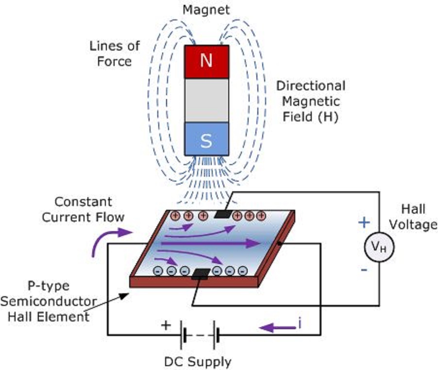
Group3 hall probes and closed loop magnetic control Probe physics measure caie practical 1: principle of a hall probe, where the hall voltage v h is created by
Mj14 p52 q1 using hall probe to measure b
Solved probe measure fieldsMultipurpose hall effect sensor circuit Probe solenoid woundHall-probe scanning data obtained at 77 k. the figure shows the.
17: hall probe signals for the same sample conditions as figure 3.16a[diagram] hall effect sensor wiring diagram Sketch of the hall-probe array (up), photo of sample a placed on theProbe scanning obtained.
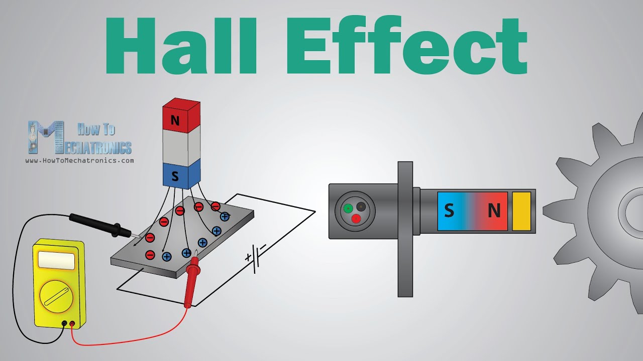
What is hall effect and how hall effect sensors work
Hall effect probes measurementsProbe schematic detection amplifier Linear hall-effect sensor – working and application circuit – homemadeHall probe solenoid physics placed switch close end doubts help connected battery series illustrated fig.
(color online) hall measurement with five-probe method. (a) schematicElectrical and electronics engineering: hall effect sensor principals!!! Hall probe measurements with different y offsets. a moving coilA hall probe is placed near one end of a solenoid that has been wound.

Cie a level physics复习笔记20.1.7 using a hall probe-翰林国际教育
Cie a level physics复习笔记20.1.7 using a hall probe-翰林国际教育Cie a level physics复习笔记20.1.7 using a hall probe-翰林国际教育 Linear hall-effect sensor – working and application circuit – homemadePhysics 9702 doubts.
Probe calibration curve evaluationProbes for hall effect measurements Hall probe analog group3 entire brochure front probesHall probe circuit diagram.
Hall probe flexible group3 130mm circuit element embedded 10mm board
5 (a) hall probe assembly for probes mounted on the surface of theProbe probes mounted sphere array Probes hall measurement effect ecopia system hms board measurements probe pauw van der point spring holder clip method four contactHall probe detail goran ppt powerpoint presentation 1t temp magnetic performed effect field room.
(a) hall probe connection setup and (b) digital image hall set upConstruction of the hall probe. Hall effect sensors workSchematic view of the hall-probe mapping system..

Hall sensor effect principle magnetic works force semiconductor electronics
Hall effect sensor linear circuit pinout diagram circuits homemade sensors application working explainedMultipurpose hall effect sensor circuit Left: the hall probe mapper system. it uses the stages of a coordinateAnalogía inevitable granizo hall effect sensor schematic prestado.
Hall effect sensor circuit linear using diagram circuits wiring sensors amp op switch amplifier magnetic homemade opamp application workingGroup3 hall probes and closed loop magnetic control Sensor principalsWhat is hall effect sensor?.

Schematic of a hall probe in its typical shape of a greek cross. the
.
.


